Geological Explorations Museum (GEM)
48-510 Architecture Design Studio: Advanced Synthesis Options Studio III, Terraforming under the guidance of Laura Garofalo; Spring 2024
View the process book here.
01 INTRODUCTION
The intention behind our design was to create a museum that is influenced by three geological processes. These processes weave their way into the form of our building and our facade to generate a system that is energy efficient and nurtures circulation.
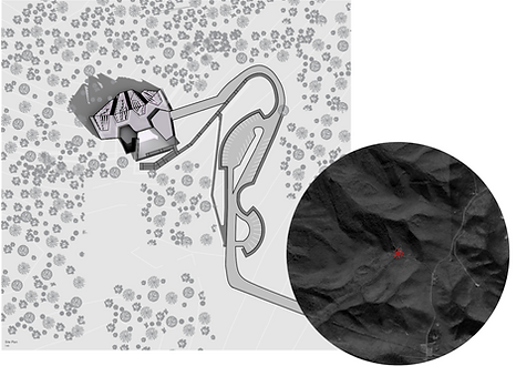
Our Site
Our site is located at Laurel Caverns, a cave site 50 miles south of Pittsburgh, PA. The cave operates from late April to October and is cloesd during the winter due to the bat hibernation season. With this in mind, we have designed our building to best perform in the spring, summer, and fall seasons.
02 PRECEDENT STUDIES
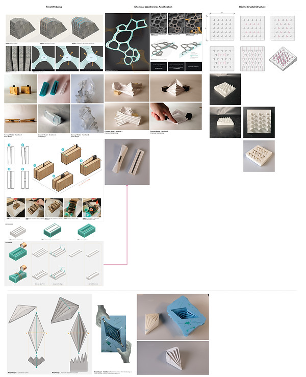
Frost Wedging
Frost wedging is a process in which rain falls into the cracks of a rock. When the temperature drops below freezing, the water within those cracks freezes and expands. When they expand, they make the cracks within those rocks bigger. We took inspiration of this wedging nature into the formation of our facade system and building formation (where each "gem" is wedged into circulation corridor)
.
Chemical Weathering: Acidification
Chemical weathering is where acidic rain falls onto rock formation and develops puddles at low points. Due to the acid, those puddles erode over time and eventually create a node and branch system. We took inspiration from the node and branch system for the layout of our facade system.
Olivine Crystal Structure
The olivine crystal structure is made of fairly triangular elements and has patterns that change in scale. We took inspiration from the geometric property and the directional aspect. Our facade system changes direction with the more triangular elements.
03 MASSING & BUILDING FORMATIONS
Massing Model
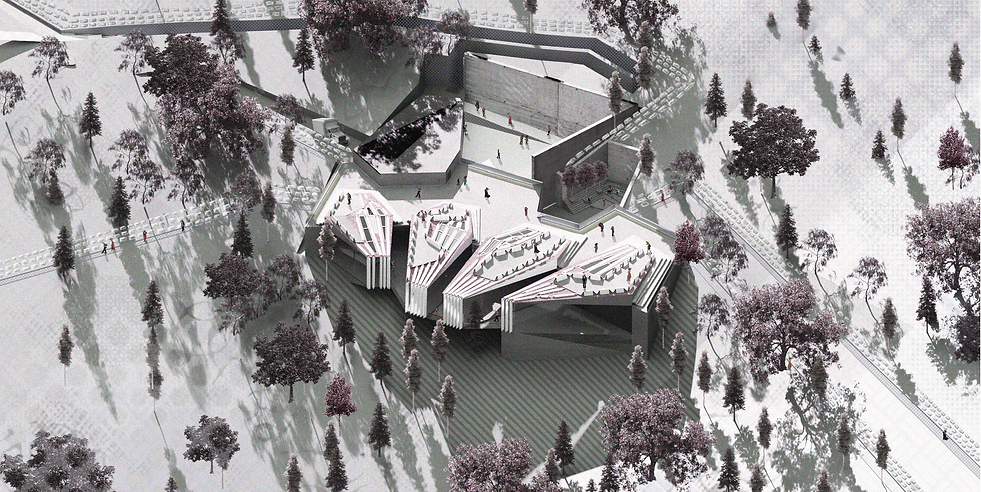
Our site is at Laurel Caverns in Pennsylvania. Our building sits where an existing building was located. We have also demolished one of the existing parking lots and have added additional parking. In relation to the site, our building hugs the contour of the landscape, aligning with the slope. Also aligning with the contours are the trails. We have several trails that stretch out from our building - we'll get into this at a later time.


Our massing model is at a 1/16” = 1’-0” scale.
Massing Diagram
The initial massing idea is derived from the precedent studies - specifically the node and branch system from the chemical weathering process, the wedging of the "gems" into the circulation corridor from the frost wedging process, the change of scale of the gems from the olivine crystal structure.

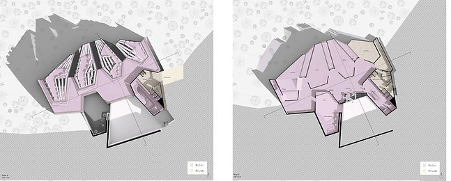
Floor Plans
The initial massing idea is derived from the precedent studies - specifically the node and branch system from the chemical weathering process, the wedging of the "gems" into the circulation corridor from the frost wedging process, the change of scale of the gems from the olivine crystal structure.


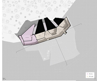
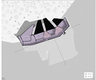
Plan Diagrams
Public vs Private: Public spaces located in the West, private spaces located in the East.
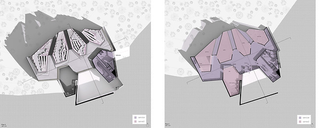
Service vs Served: Staircases are located at each end in the building (west and east). The massing has a direct impact on the
organization of the servive vs served space. Typically, what is being “wedged into” (the corridor) is the service space whereas
the served space as the gems with defined programmatic elements.
Elevations
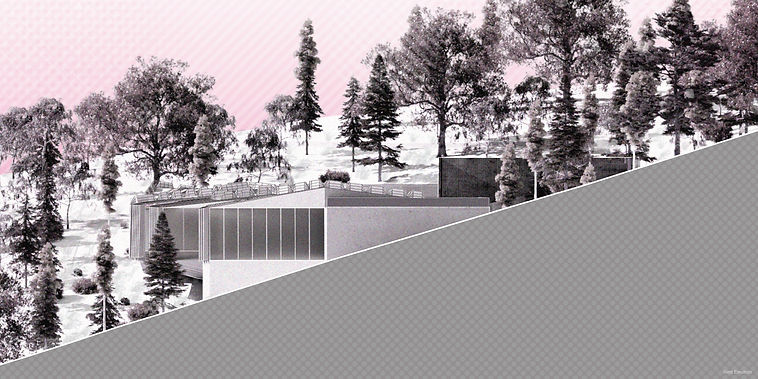
West Elevation: In our west elevation, we demonstrate how the building sits on the landscape. The gems are mostly cantilevered towards the view whereas the cave gem sits on the ground. You can also see the gem-like structure of our roof forms, reminiscent of the olivine crystal structure.
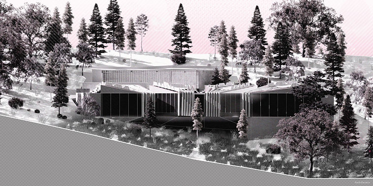
North Elevation: In our north elevation, you can see more of your glazing strategy with the gems facing the landscape.
Sections

Short Section: The public courtyard is shown on the left side. It is embraced by a large retaining wall. Not shown are the ramps that encompass the wall. This gem in particular cantilevers off of the ground. The basement spaces are enclosed to receive little to no daylight due to the programmatic conditions (research facilities).
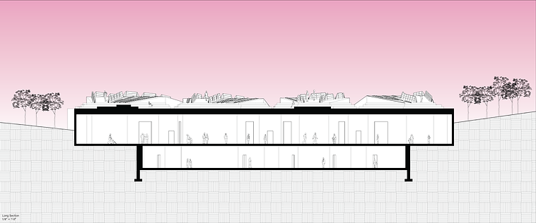
Long Section: The roof of each gem is occupiable. Visitors can access the roof through the service gem (where main entrance is located). The facade system scales vertically to act as railings
Perspectives


04 THE FACADE

Matrix to Landscape
Our facade creates 5 different trails:
-
Trail 1: goes to the parking lot
-
Trail 2: goes to the loading dock
-
Trails 3-5: goes to nature
The goal of our facade stretching out is to maximize the experience and bleed into the landscape. The experience at Laurel Caverns should encompass the natural element.

Roof Matrix
The changes from our base to final iteration are as follows:
-
Skylights: tapered to regulate the amount of sunlight coming into the building; gets narrower towards the south to reduce excessive heat gain; are scattered and distributed on the office space gem in order to ensure adequate sunlight levels
-
Walkable spaces: are placed to allow for more daylight into each gem


Roof Matrix - Climate Studio
We strategically made iterations based on our Climate Studio results.
-
Baseline: Massing with default properties (walls, glazing) || We had enough daylight, but there were glare issues
-
Iteration 1: Addition of skylights || Resulted in more glare problems
-
Iteration 2: Addition of facade, shading devices, and operable blinds || Received less light, but eliminated our glare problem
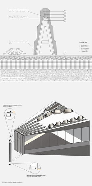
Assembly Details
Facade unit to the building: The facade units are clipped to the timber support structure (each casted terracotta unit is fairly heavy, thus limiting the need for more complex attachment systems). Rubber gaskets are added in between them to prevent the facade from clashing against the support structure (ex. harsh wind may cause this). The support structure is then anchored down to the roof surface with the roof surface having a gravel bed for rainwater release.
Shading devices to the window mullions: Metal plates are clipped in between each shading device and the end facade units. Plates are also attached to the building itself.)

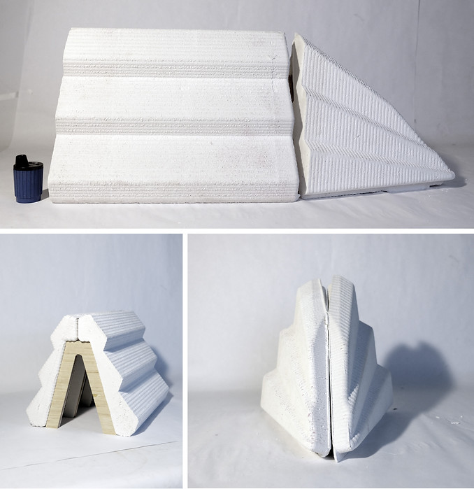
1:3 Prototype
Here's how we made our prototype:
-
Create our molds with the CNC router || We developed various patterns using the CNC router. Our strategy was to create a two-part mold in order to easily remove our cast.
-
Prepare the molds || To prepare the molds, we used a mold release spray and let it soak into the molds for 15-30 minutes. After spraying the molds, we taped the halves together.
-
Cast! || We then casted the molds using a 1:1 ratio of plaster to water and poured the solution into each mold.
In the real world, we expect the facade to be developed by an extrusion.

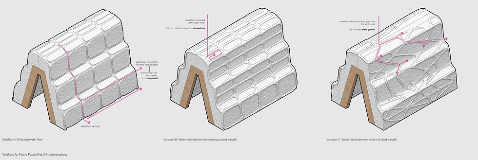
Future Implementations
As we near the end of this project, we asked ourselves...How could we have taken this project further? What other life can we foster?
We developed 3 strategies of future implementations:
-
Variation A: Directing water flow || Water flows vertically down the facade and horizontally, dependent on the roof slope. With his sort of strategy, we can collect rainwater to be repurposed.
-
Variation B: Water collection || This strategy collects water in each “hole”. We imagine this can facilitate more homogenous plant growth.
-
Variation C: Water distribution for a variety plant growth || Different from the previous variations, variation C utilizes a more randomized approach. This allows for rainwater to be distributed throughout the system and encourage more variety of plant growth.
B.02 FRAMING UNMAKING
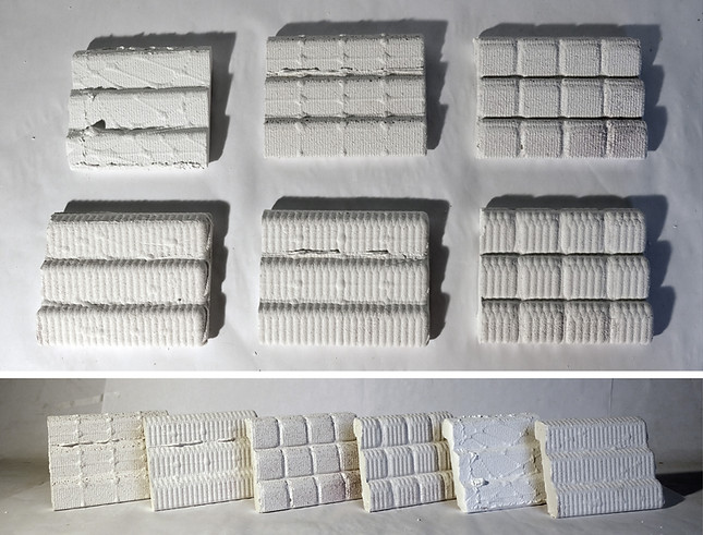
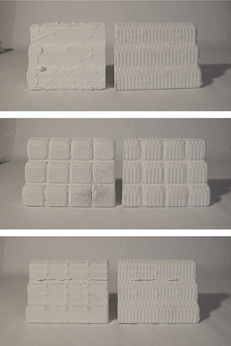
Future Implementations - 1:4 Study Models: We took the following three textures and made mockups of what they might look like in real life. We also played around with using different bit sizes of the CNC router (1/8" vs 1/4") to see what other variations we could create.
Project in collaboration with Andrew Yoon